31+ uml diagram entity relationship
The Internet or internet is the global system of interconnected computer networks that uses the Internet protocol suite TCPIP to communicate between networks and devices. It is a network of networks that consists of private public academic business and government networks of local to global scope linked by a broad array of electronic wireless and optical networking.

Art Gallery Database Management System Er Diagram 34 Pages Explanation In Doc 1 9mb Updated Learn With Jordan
Hi I have to do an ER model for a travel game app but we have not been shown how in college.
. This type of diagrams is used in Component-Based Development CBD to describe systems with Service-Oriented Architecture SOA. Our global writing staff includes experienced ENL ESL academic writers in a variety of disciplines. The entity-relationship diagram of Banking Management System shows all the visual instrument of database tables and the relations between Employees Fixed Deposit Customer Current Account etc.
I want a relationship between er diagram and uml diagram. This is a Component diagram of Hospital Management System which shows components provided and required interfaces ports and relationships between the Patient Doctor Appointment Medicines and Hospital. One of the first uses of the term protocol in a data-commutation context occurs in a memorandum entitled A Protocol for Use in the NPL Data Communications Network written by Roger Scantlebury and Keith Bartlett in April 1967.
6 to 30 characters long. In my previous article on sequence diagrams I shifted focus away from the UML 14 spec to OMGs Adopted 20 Draft Specification of UML UML 2In this article I will discuss Structure Diagrams which is a new diagram category that. UML Diagram Generator for XrmToolBox is a tool that generates Entity Relationship Diagrams in the form of PlantUML files from metadata in Microsoft Dynamics 365 and the Power Platform Dataverse.
It is also possible to add support for new shapes by writing simple XML files using a subset of Scalable Vector Graphics SVG to draw the shape. This lets us find the most appropriate writer for any type of assignment. It can be used to draw many different kinds of diagrams.
In other words ER diagrams illustrate the logical structure of databases. The secondary challenge is to optimize the allocation of necessary inputs and apply. Irrespective of whether they are object models eg.
This information is usually described in project documentation created at the beginning of the development processThe primary constraints are scope time and budget. Payroll Management System 1519BEIT30052 12 HR consultancy. The key purpose of the Logical Data diagram is to show logical views of the relationships between critical data entities within the enterprise.
Must contain at least 4 different symbols. The creation of UML was originally motivated by the desire to standardize the disparate notational systems and approaches to software design. The first are primitive interrogatives.
What How When Who. Get 247 customer support help when you place a homework help service order with us. Very clearly explained.
The 1980s were years of relative consolidation. Using UML entity relationship models or XML schemas. There are many tools that are more sophisticated than MS Access for making diagrams on a larger scale.
This diagram is developed to address the concerns of. The ontology is a two dimensional classification schema that reflects the intersection between two historical classifications. UML 25 shape library with updated shapes.
ASCII characters only characters found on a standard US keyboard. As the result is text-based files they can be manually edited and kept in source control for change tracking over time. Project management is the process of leading the work of a team to achieve all project goals within the given constraints.
Dia has special objects to help draw entity-relationship models Unified Modeling Language UML diagrams flowcharts network diagrams and simple electrical circuits. An Entity Relationship Diagram. He described how this technique was used at Ericsson to capture and specify requirements of a system using textual structural and visual modeling techniques to drive object oriented analysis and design.
It used structure data and to define the relationships between structured data groups of Airline Booking System functionalities. This is a Component diagram of Railway Reservation System which shows components provided and required interfaces ports and relationships between the Train Schedule Ticket Booking Customer and Payment. This is the next installment in a series of articles about the essential diagrams used within the Unified Modeling Language or UML.
Originally he had used the terms usage scenarios and usage. This will be fairly complete if the database builder has identified the foreign keys. On the ARPANET the starting point for host-to-host communication in 1969 was the 1822 protocol which defined.
This is a Component diagram of Library Management System which shows components provided and required interfaces ports and relationships between the Issues Student Librarian Member and Address. An entity relationship diagram ERD shows the relationships of entity sets stored in a database. An entity in this context is a component of data.
It currently has special objects to help draw entity relationship diagrams UML diagrams flowcharts network diagrams and many other diagrams. Document Object Model a standard object model for representing HTML or. Dia is roughly inspired by the commercial Windows program Visio though more geared towards informal diagrams for casual use.
Simplified UML class diagrams. The Zachman Framework is an enterprise ontology and is a fundamental structure for enterprise architecture which provides a formal and structured way of viewing and defining an enterprise. UML Diagram Generator.
The United States government standardized Ada a systems programming language derived from Pascal and intended for use by defense contractors. UML notation is the defacto industry standard in the fields of software development IT infrastructure business systems and other fields. Can anyone please give me some ideas on how to go about this.
The entity-relationship diagram of Airline Booking System shows all the visual instrument of database tables and the relations between Airlines Booking Ticket Ticket Airline Enquiry etc. In Japan and elsewhere vast sums were spent investigating the so-called fifth-generation languages that. It used structure data and to define the relationships between structured data groups of Banking Management System functionalities.
This type of diagrams is used in Component-Based Development CBD to describe systems with Service-Oriented Architecture SOA. In 1987 Ivar Jacobson presented the first article on use cases at the OOPSLA87 conference. An entity-relationship model ERM sometimes referred to as an entity-relationship diagram ERD could be used to represent an abstract conceptual data model.
C combined object-oriented and systems programming. The Unified Modeling Language UML is a general-purpose developmental modeling language in the field of software engineering that is intended to provide a standard way to visualize the design of a system. We will guide you on how to place your essay help proofreading and editing your draft fixing the grammar spelling or formatting of your paper easily and cheaply.
This type of diagrams is used in Component-Based Development CBD to describe systems with Service-Oriented Architecture SOA. Library Management System UML. The Unified Modeling Language UML is a set of standard symbols and diagram types commonly used in data modelling workflow visualisation and system modelling.
Perhaps the simplest is the Relationship Diagram that MS Access can produce from a completed database.

Art Gallery Database Management System Er Diagram 34 Pages Explanation In Doc 1 9mb Updated Learn With Jordan

Entity Relationship Diagram Erd Library Relationship Diagram Relationship Diagram Design

An Entity Relationship Diagram Showing A Structured Approach To Defining A Metadata Information Architecture Software Architecture Design Relationship Diagram
Diagram Template 18 Free Word Pdf Documents Download Free Premium Templates

How Can I Model A Medical Scenario In An Entity Relationship Diagram Relationship Diagram Diagram Design Diagram

Art Gallery Database Management System Er Diagram 34 Pages Explanation In Doc 1 9mb Updated Learn With Jordan

Art Gallery Database Management System Er Diagram 34 Pages Explanation In Doc 1 9mb Updated Learn With Jordan

424h
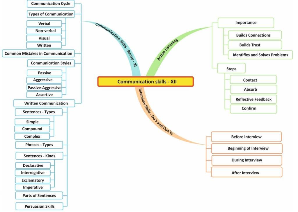
Communication Skills Class 12 Notes Cbse Skill Education

Art Gallery Database Management System Er Diagram 34 Pages Explanation In Doc 1 9mb Updated Learn With Jordan

Entity Relationship Diagram Common Erd Symbols And Notations Relationship Diagram Diagram Erd
Expanding A Database Derived Biomedical Knowledge Graph Via Multi Relation Extraction From Biomedical Abstracts

Entity Relationship Diagram Erd Er Diagram Tutorial Relationship Diagram Activity Diagram Tutorial

Class Diagram For Dental Clinic Management System 50 Pages Explanation In Doc 1 7mb Updated 2021 Violet Study For Exams

Communication Skills Class 9 Notes 2022 Cbse Skill Education

Entity Relationship Diagram Er Diagram Showing A Learning Management System Click On The Image To Us Relationship Diagram Learning Management System Diagram

Art Gallery Database Management System Er Diagram 34 Pages Explanation In Doc 1 9mb Updated Learn With Jordan